
The Peregrine project was started in 2020 to build a smaller and more affordable system than those attempted previously, now made possible by advances in fixed-wing UAVs and miniaturized electronics.
We knew we couldn’t do the IPR with off-the-shelf systems. We had to start with a blank slate to develop a system that was small and light enough to fit on an inexpensive UAV.
We decided to use software-defined radio (SDR) technology for our radars because these RF transmitters and receivers are highly customizable and shift much of the complexity of the system from hardware to software. Using an SDR, an entire radar system can fit on a few small circuit boards.
From the start, we looked beyond our first project, developing software built on top of Ettus’s USRP Hardware Driver application programming interface, which can be used with a variety of software-defined radios, ranging in cost from US $1,000 to $30,000 and in mass from tens of grams to multiple kilograms.
We added a Raspberry Pi single-board computer to control our software-defined radio. The Raspberry Pi also connects to a network of temperature sensors, so that we could be sure nothing in our system gets too hot or too cold.
The SDR itself has two sides to it, one for transmitting the radar signal and one for receiving the echoes, each connecting to our custom-made antennas through amplifiers and filters. This entire system weighs a little under 1 kilogram.
Those antennas were tricky to design. IPR antennas require relatively low frequencies (because higher frequencies are more significantly attenuated by ice) and have relatively wide bandwidths (to achieve sufficient range resolution). Normally, these criteria would mean a large antenna, but our small UAV couldn’t handle a big, heavy antenna.
I started by considering a standard bowtie antenna, a type commonly used in ground-based radar systems. The initial design was far too large to fit even one antenna, much less two, on our little UAV. So using a digital model of the antenna, I adjusted the geometry to find an acceptable compromise between size and performance, at least according to the simulation software I was using.
I also built several prototypes along the way to understand how real antenna performance might differ from my simulations. The first of those I made from copper tape cut and pasted onto sheets of plastic. The later and final versions I fabricated as printed circuit boards. After a few iterations, I had a working antenna that could be mounted flat under each wing of our diminutive aircraft.
Thomas Teisberg, an electrical engineering Ph.D. candidate at Stanford University, launches Peregrine at Norway’s Slakbreen glacier.
For the drone, we started with a kit for an X-UAV Talon radio-controlled plane, which included a foam fuselage, tail assembly, and wings. We knew that every piece of conductive material in the aircraft would affect the antenna’s performance, perhaps in undesirable ways. Tests showed that the carbon-fiber spar between the wings and the wires to the servo motors in each wing were creating problematic conductive paths between the antennas, so we replaced the carbon-fiber spar with a fiberglass one and added ferrite beads on the servo wiring to act as low-pass filters.
Fighting Noisy Signals
I thought we were ready. But when we took our UAV out to a field near our lab, we discovered that we could not get a GPS fix on the drone when the radar system was active. After some initial confusion, we discovered the source of the interference: our system’s USB 3.0 interface. To solve this problem, I designed a plastic box to enclose the Raspberry Pi and the SDR, 3D-printed it, and wrapped it in a thin layer of copper tape. That shielded the troublesome USB circuitry enough to keep it from interfering with the rest of our system.
Finally, we were able to fly our tiny radar drone over a dry lakebed on the Stanford campus. Although our system cannot image through dirt, we were able to get a strong reflection off the surface, and at that point we knew we had a working prototype.
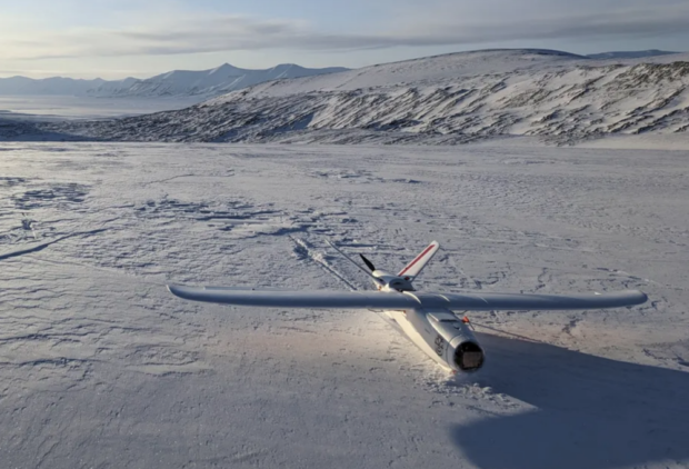
Peregrine lands after a test flight in Norway
We carried out our first real-world tests six months later, on Iceland’s Vatnajökull ice cap, thanks to the help and generosity of local collaborators at the University of Iceland and a grant from NASA. That was a good spot, because from time to time, a nearby volcanic eruption spews volcanic material known as tephra over the surface of the ice cap. That tephra eventually gets buried under new snow and forms a layer under the surface. We figured these strata would serve as a good stand-in for the internal layering found in ice in Greenland and Antarctica. Although an abundance of liquid water in the relatively warm Vatnajökull ice prevented our system from probing more than tens of meters below the surface, these tephra layers were apparent in our radar soundings.
But these first trials did not go uniformly well. After one of our test flights, I discovered that the data we had collected was almost entirely noise. We tested every component and cable, until I found the shield on one of the coaxial cables had broken and was only intermittently making a connection. With a spare cable and a generous application of hot glue, we were able to complete the rest of our testing.

As Peregrine climbs into the air over the Slakbreen glacier, the system’s red antennas are clearly visible under the wings – ELIZA DAWSON
For our next round of tests, we were aiming to image bedrock under a glacier, not just internal layers. And that’s why, in March of this year, we ended up on a glacier in the coldest part of Norway, where liquid water within the ice was less likely to interfere with our measurements. There we were able to image the bed of the glacier, as much as 150 meters below the surface where we were flying. Crucially, we also convinced ourselves that our system will work properly in the harsh environments we expect it to face in Antarctica and Greenland.
A Drone Fleet Across Antarctica
Our present system is relatively small. It was designed to be inexpensive and portable so that research teams can easily bring it along on expeditions to far-flung spots. But we also wanted it to serve as a testbed for a larger UAV-borne IPR system with an operational range of about 800 km, one that is inexpensive enough to be permanently deployed to Antarctic research stations. With the 11 existing research stations as bases, at least one member of such a drone fleet could access nearly every part of coastal Antarctica. Though larger and more expensive than our original Peregrine, this next-generation UAV will still be far cheaper and easier to operate than crewed airborne systems are.
Operating a larger UAV, much less a fleet of them, is beyond what a few Ph.D. students alone can reasonably do, so we are launching a collaborative effort between Stanford University, the Scripps Institution of Oceanography, and Lane Community College, in Eugene, Ore., to get this new platform off the ground. If all goes well, we’re hoping we can have IPR UAVs surveying the Antarctic and Greenland ice sheets within three years. Doing so would no doubt help scientists studying the responses of Earth’s ice sheets to climate change. With permanently deployed UAVs able to cover most areas of active study, requests for new data could be fulfilled within days. Surveys could be repeated at frequent intervals over dynamic areas. And when rapid and unpredictable events occur, such as the collapse of an ice shelf, a UAV could be deployed to gather real-time radar data.
Such observations are just not possible today. But Peregrine and its successors could make that possible. Having the ability to collect this kind of radar data would help glaciologists resolve fundamental uncertainties in the physics of ice sheets, improve projections of sea-level rise, and enable better decision making about mitigations and adaptations for Earth’s future climate.
Photo: Peregrine, a drone-based ice-penetrating radar system, was tested over Norway’s Slakbreen glacier in March – ELIZA DAWSON
Source: IEEE Spectrum