
 Virtually all current imaging methods rely on light traveling directly from the object to be imaged to the imaging device. Although direct, ballistic, single-bounce light components generally make up a large portion of the total light that is collected by an imaging system, there is a significant contribution from multi-bounce light. This light is scattered or reflected by surfaces in the scene multiple times on the path from light source to detector.
Depending on the amount of scattering in the scene, the multi-bounce component can be significantly larger than the direct component, and is typically much more complex. Current imaging techniques aim to remove this information from the data to create images using the remaining ballistic-light component.
Our imaging system recovers information in non-ballistic light, enabling objects that would be obscured in typical imaging systems to be detected. To do this, it uses photon time-of-flight information (i.e., the time taken for light to travel through a scene from an active, time-modulated source to a fast detector). By analyzing this additional piece of data, we can obtain information about the multi-bounce behavior of the light.1, 2 Possible applications of this technique range from seeing around corners in scenarios with only limited scattering, to imaging an object that is obscured by bulk scattering materials (e.g., tissue or fog).
Figure 1 shows a time-of-flight imaging system probing a scene via the reflection from a laboratory wall. The visible relay surface in the scene (in this case, the wall) is illuminated by a pulsed light source, such as a picosecond-pulsed laser. The detector, focused on a portion of the visible relay surface that is not directly illuminated, detects the scattered light that has been reflected multiple times within the scene. In this setup, the detected signal consists of light that has undergone three or more reflections. The detector records the intensity of this incoming light with picosecond time resolution. Time responses of the scene are recorded in this fashion for different illuminated points. An image of the hidden object can then be computed from this data by using a custom-filtered back-projection algorithm.1, 3,4
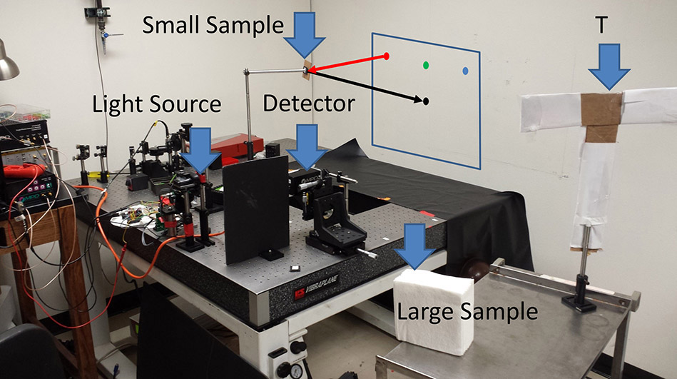
Figure 1. Our laboratory setup and the scene to be imaged. Light is sent from the light source to one of a set of points on the wall (indicated by the red, green, and blue dots). Light reflects from these points, interacts with the scene, and returns to the wall. The detector is focused on the area on the wall indicated by a black dot.3The sample targets (large sample, small sample, and a letter T) are made of white paper with cardboard frames.
Our algorithm enables the scene to be reconstructed by computationally back-projecting the path of every detected photon via a set of points in the scene that enable the hidden scatterer to be located. This set of points is constrained by known properties of the photon: the point in the visible scene from where it was emitted ![]() ; the point in the visible scene where it was detected
; the point in the visible scene where it was detected ![]() ; and the time taken traveling between the two
; and the time taken traveling between the two ![]() . The set of coordinates collected for a particular photon
. The set of coordinates collected for a particular photon 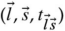 is projected onto an ellipsoid in the hidden-volume reconstruction. After back-projection of a large number of photons with a variety of parameters, a 3D rendering of the scene can be achieved (see Figure 2).
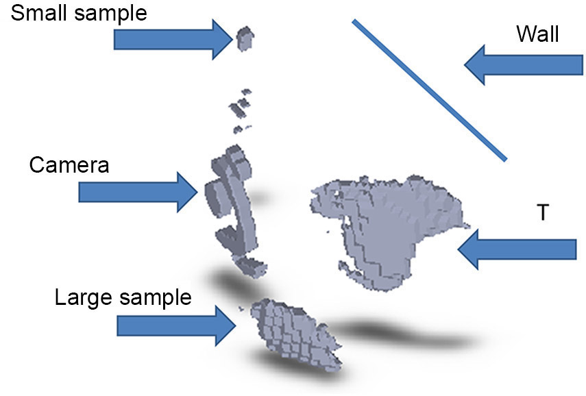
igure 2. Reconstruction of the laboratory scene, obtained using our back-projection algorithm. The back-projection result is filtered using a high-pass filter and thresholded to provide a 3D rendering of the scene.3
The capture-hardware requirements for non-line-of-sight imaging are different from those used in regular cameras, 3D imaging, or LiDAR sensors. Sensors such as these are designed to image relatively bright first-bounce light, whereas non-line-of-sight imaging requires the detection of significantly weaker third-bounce signals. Because our sensors must capture significantly more complex temporal profiles, they also require time resolutions that are orders of magnitude higher than those of time-of-flight 3D scanners. Gated single-photon avalanche-diode (SPAD) detectors satisfy both of these requirements due to their high time resolution, dynamic range, and excellent signal-to-noise ratio. Our SPAD detector, built by the group of Alberto Tosi at the Politecnico di Milano,5 provides 20-picosecond resolution with a dark-count rate of less than 10 photons per second. The gating function allows the detector to be activated within a few hundred picoseconds.
In summary, our time-of-flight imaging system enables the indirect observation of hidden scenes via computational back-projection. Applications for this non-line-of sight technology range from small scenes (e.g., robotic or laparoscopic surgeries), to intermediate scales (e.g., remote detection of individuals for disaster response and law enforcement), to very large scenes (e.g., aerial and satellite surveillance). Together with Jeffrey Nosanov and Karl Mitchell at the Jet Propulsion Lab, we are currently exploring the imaging of lunar caves from an orbiting platform. Other applications lie in vehicle navigation, robotics, manufacturing, and automation.
This work was supported by the NASA Innovative Advanced Concepts program, and by the US Defense Advanced Research Projects Agency under the Revolutionary Enhancement of Visibility by Exploiting Active Light-fields (REVEAL) program.
University of Wisconsin-Madison
Andreas Velten received his PhD in physics from the University of New Mexico in 2009, and subsequently completed his postdoc at the MIT Media Lab. He was chosen as one of the 35 top innovators under 35 by MIT Technology Review in 2012.